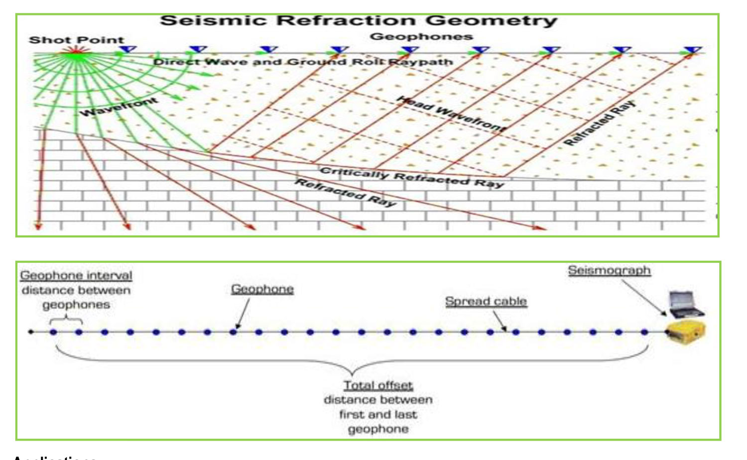
Seismic refraction is a valuable tool for mapping bedrock and fractures. It is usually more cost-effective and gives better coverage than drilling alone. The seismic refraction method utilizes sound waves. Sound travels at different velocities though different materials and is refracted at layer interfaces. A seismic wave is usually generated using a sledge hammer, a specially designed seismic gun that employs a blank shotgun shell, or a seismic weight drop tool. The wave’s travel time from the sound source to refracting layers, along those layers and back to detectors (called geophones) is precisely measured. From the time-distance relationships, subsurface layer velocities and thicknesses can be calculated. Fracture zones can often be detected because they usually have a lower seismic velocity than solid bedrock. The velocity of sound through water saturated material is about 1524 m per second while the velocity though crystalline bedrock generally ranges from 3660 to 5500 m per second. By calculating the velocity of sound along the bedrock surface, low velocity zones, which may represent fractures, can be delineated.
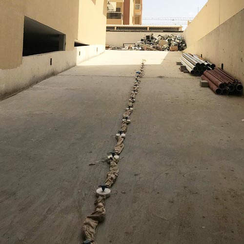
Our system utilizes up to 24 geophones at one time. The geophones can be linearly spaced any distance apart, but most often are spaced 10 to 50 feet apart. In general the greater the expected bedrock depth, the greater the geophone spacing. Shorter spacing and sometimes radial patterns are used in fracture zone detection studies. Final results are provided to the client in a full report which includes tables of subsurface depths and elevations, and cross-section profiles. Results are also available as bedrock contour maps and on computer disks.

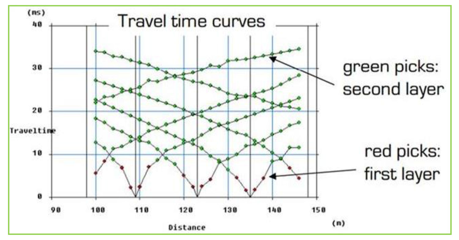
Data Processing Software Samples